FAQ
- Photovoltaic
- How and with what voltage can we measure the PV installation resistance?
Measure the insulation resistance between the positive pole (DC+) and ground, and between the negative pole (DC-) and ground. It is one of two the two methods authorised by EN 62446.
In systems of up to 10kWp, use the measuring voltage provided in the table below:
- Does the Sonel MPI-540-PV meter automatically adjusts the measurement result do STC conditions?
Yes. The meter automatically adjusts the Isc ,Uoc measurement results to STC conditions. The precondition for the adjustment of the calculations is the input of the PV module parameters and the values of panel irradiation and temperature or ambient temperature. The value of irradiation and temperature may be measured using the Sonel IRM-1 adapter. If there is no IRM-1, the data may be manually entered to the meter.
- What standard includes guidelines for performing PV system measurements?
One of the most important standards describing the requirements regarding PV system testing is EN 62446.
- What PV system measurements can be performed using MPI-540-PV?
Sonel MPI-540-PV enables the measurement of the following PV system parameters according to PN-EN 62446 (cat. 1):
- continuity of protective connections,
- resistance of ground,
- insulation resistance on the DC side,
- open circuit voltage UOC
- short-circuit current ISC
- operating currents and power on the DC and AC side,
- inverter efficiency.
Apart from the above it is also possible to perform electrical installation parameters on the AC side according to EN 60364.
- What is the difference between MPI-540-PV and MPI-540-PV Solar?
The MPI-540-PV Solar set features additional accessories for the measurement of irradiation and temperature in photovoltaic systems – see the table.
The basic differences between the multifunctional meters with a touch screen
MPI-535 MPI-536 MPI-540 MPI-540-PV MPI-540-PV Solar Measurements of PV system input parameters (IEC 60364) v v v v v Three-phase power quality logger v v v Measurements of PV systems (EN IEC 62446 cat I) v v Measurements of panel irradiation and temperature, and ambient temperature in PV systems v Advanced insulation resistance measurement (with 2.5 kV, graphs, absorption coefficients, temperature coefficients) v “Start” version of a given model does not include the Sonel F-3A flex clamps - What are the differences between the Sonel PVM-1020 meter and the Sonel MPI-540-PV meter?
PV system tests per IEC 62446-1 (Cat. 1) Sonel PVM-1020 Sonel MPI-540-PV Short-circuit current, Isc Yes (directly) Yes (with the PVM-1 adapter and test clamps incl. with the meter) Open circuit voltage, Uoc Yes (directly) Yes (with the PVM-1 adapter incl. with the meter) Protective and equipotential conductor continuity resistance, Rcont Yes Yes PV Riso Riso+, Riso- (2 automatic tests) Riso+, Riso- (2 separate tests) DC line current clamp test Yes (test clamps incl. with the meter) Yes (test clamps incl. with the meter) Polarity check Yes Yes Bypass diode test Yes No Lockout diode test Yes No Earthing measurement No Yes AC current clamp test Yes Yes AC/DC power test Yes Yes Sound-indicated continuity test, Rx Yes Yes AC Riso Yes Yes Inverter efficiency test No Yes Optional features Sonel PVM-1020 Sonel MPI-540-PV Irradiance & temperature meter interaction (LoRa) Yes Yes Measurement result conversion to STC Yes Yes PV panel base No Yes Successive PV chain-to-chain test error calculation Yes Yes Selftest Yes (one defined) Yes (multiple, user-defined) Successive PV chain-to-chain test error calculation Sonel PVM-1020 Sonel MPI-540-PV Rx and Rcont testing Yes Yes Insulation resistance, Riso Yes Yes Short-circuit loop impedance, Z No Yes RCD performance parameters No Yes Earthing resistance and soil resistivity, Re No Yes TKF, motor spin No Yes Luxometer No Yes EVSE testing No Yes Three-phase power quality logger No Yes Other parameters Sonel PVM-1020 Sonel MPI-540-PV Ingress protection IP 65 IP 51 Display 3.5” monochrome graphical display 7” touch-screen graphical colour display Memory 4,500 records of capacity at least 100,000 records of capacity Power supply 4 x AA (disposable batteries or NiMh cells) Li-ion battery Casing dimensions 228 x 102 x 61 mm 288 x 223 x 75 mm Meter weight (w/o accessories) ca. 1 kg ca. 2.5 kg - What is the difference between Sonel MPI-540-PV and Sonel MPI-540?
The Sonel MPI-540-PV meter features additional functions and accessories for PV system measurements – see the table.
The basic differences between the multifunctional meters with a touch screen
MPI-535 MPI-536 MPI-540 MPI-540-PV MPI-540-PV Solar Measurements of PV system input parameters (IEC 60364) v v v v v Three-phase power quality logger v v v Measurements of PV systems (EN IEC 62446 cat I) v v Measurements of panel irradiation and temperature, and ambient temperature in PV systems v Advanced insulation resistance measurement (with 2.5 kV, graphs, absorption coefficients, temperature coefficients) v “Start” version of a given model does not include the Sonel F-3A flex clamps - Is it possible to upgrade the Sonel MPI-540-PV meter to MPI-540-PV Solar version?
Yes, it is. It is not necessary to change the software. The Solar version comes with additional accessories and adapters for measuring the PV panel irradiation and temperature as well as ambient temperature. The set of the necessary accessories to be purchased separately is available here.
- Does the Sonel MPI-540-PV meter allow to determine the I/V current-voltage characteristics (so called I/V curve) of photovoltaic panels?
The Sonel MPI-540-PV meter does not have the function of determining the I/V current-voltage characteristics. They are category II measurements according to EN 62446 regarding the assessment of PV system efficiency. Sonel MPI-540-PV enables category I measurements according to EN 62446 regarding system safety.
- How and with what voltage can we measure the PV installation resistance?
- Electromobility
- What is the single-phase socket on the EVSE-01 housing used for?
The single-phase socket on the Sonel EVSE-01 housing is used for single-phase station measurements using the WS-03/WS-05 adapter.
- What is the difference between the Sonel EVSE-100 and the Sonel EVSE-01?
The Sonel EVSE-01 is an adapter that requires a multifunction meter to perform measurements on stationary AC charging stations. The Sonel EVSE-100 is a multifunction analyzer dedicated to performing measurements on stationary AC charging stations, portable charging stations, and charging cables. The Sonel EVSE-100 also features a multifunction meter mode, allowing for low-voltage installation measurements using test leads.
- What types of electric vehicle charging stations can be tested with the Sonel EVSE-100 analyzer?
The Sonel EVSE-100 multifunction analyzer is designed for testing electric vehicle charging stations. It is intended for verifying the safety and proper operation of charging stations using charging mode 3 according to IEC 61851-1, with sockets compliant with IEC 62196 Type 2, as well as charging mode 2 according to IEC 61851-1 with Type 2 sockets. It is also intended for testing charging cables.
- Is an additional multifunction meter required for the Sonel EVSE-100 analyzer to perform measurements?
No. The multifunction analyzer for electric vehicle charging stations, Sonel EVSE-100, is a standalone device, and it allows for the complete set of electrical measurements and diagnostics to be carried out on AC-type charging stations.
- Which Sonel multifunction meters does the EVSE-01 adapter work with?
The Sonel EVSE-01 adapter works with all Sonel multifunction meters. However, it should be taken into consideration that cooperation is dependent on the measurement functions and capabilities of the model in question. Sonel MPI-535/536/540/540-PV are meter models with which we can carry out a full range of measurements.
- How can I generate a measurement report from the Sonel EVSE-100?
Using the free Sonel Reader software, measurement data can be imported to a computer in the form of simple measurement tables, with options to print and export to Excel. With the paid Sonel Reports Plus software, measurement data can be imported and a professional test report can be generated automatically.
- Is it possible to carry out a measurement protocol for electric vehicle charging stations in Sonel Reports Plus?
Yes. The Sonel Reports Plus programme offers the possibility to create a dedicated EV charging station test report.
- Which standard to choose when testing a 6mA EV RCD at an EV charging station: IEC 62955 or IEC 62752?
The IEC 62955 standard applies to charging stations operating in charging mode 3.
The IEC 62752 standard applies to portable charging cables with integrated RCD EV 6mA protection.
- Does the EVSE-01 adapter support three-phase stations?
The Sonel EVSE-01 adapter enables measurements of AC charging stations with a type 2 connector with a socket and a permanently attached charging cable. Tests of 1-phase and 3-phase stations – both with and without ventilation - are available.
- Can the EVSE-01 adapter be used to perform measurements at DC EV charging stations?
No. The Sonel EVSE-01 adapter is designed for AC-type stations only.
- Which EV charging stations can be measured with the EVSE-01 adapter?
The Sonel EVSE-01 adapter is used to measure charging stations for electric cars. It is designed to test the safety and correct functioning of charging stations in mode 3 charging according to EN-61851-1 with IEC 62196 type 2 sockets.
- Can the Sonel EVSE-100 analyzer perform measurements on DC electric vehicle charging stations?
No. The Sonel EVSE-100 multifunction analyzer is dedicated exclusively to AC charging stations and testing charging cables.
- What types of objects can be tested using the Sonel EVSE-100?
The Sonel EVSE-100 can be used to perform measurements on:
- stationary AC charging stations (wallbox/pillar – EVCS)
- portable charging stations (ICCB)
- EV charging cables
- other components of electrical installations (in multifunction meter mode)
- Do the Sonel MPI-535/536/540/540-PV meters have dedicated self-tests for testing EV charging stations?
Yes. The Sonel MPI-535/536/540/540-PV models have dedicated self-tests for testing EV charging stations. In addition to predefined sequences, the user can add their own ones.
- What measurements can be performed at the EV charging station using the EVSE-01 adapter and multifunction meter?
Using the Sonel MPI-535/536/540/540-PV and Sonel EVSE-01 adapter, diagnostics of the CP and PP control signals can be carried out. In addition, we can perform:
- short circuit loop impedance measurement (Z)
- measurement of RCD parameters (also EV 6 mA DC)
- insulation resistance measurement (Riso)
- What is the single-phase socket on the EVSE-01 housing used for?
- Applicable regulations, calibration & laboratory
- Can I start taking measurements immediately after calibration?
Please note that the calibration process is carried out for many functions and in various configurations. Before taking your first measurements, check the meter settings. The correct way to verify them is described in the user manual for the meter in question.
- Calibration with or without accreditation?
Accredited laboratories offer calibration services both with and without accreditation. How is the calibration service itself different? The calibration service with accreditation is performed according to the procedure (instruction) accepted by PCA. However, the measurements themselves, if this is to be an accredited calibration, are made repeatedly, i. e. the same parameter, on one range is checked repeatedly. Such a test is a better opportunity to determine the average measured value and its uncertainty, which is compared with the CMC of an accredited laboratory. CMC measurement capability calibration and measurement capability) is the smallest uncertainty of measurement that a calibration laboratory can achieve in a routine calibration, normally the expanded uncertainty of measurement with a level of confidence of approx. 95%. In addition, the accredited calibration certificate includes the PCA marks, which raise its status, ensure the credibility of the results, and are recognised worldwide.
- Does the lack of a calibration certificate indicate that the meter is not working properly
No. A calibration certificate is a document containing the error of measurement, i. e. the difference between the value of the reference quantity and the value of the measured quantity, as well as the uncertainty of measurement. Lack of a calibration certificate is a lack of awareness of the indications of a given measuring instrument. A current calibration certificate allows to determine metrological properties of a calibrated measuring instrument and contains corrections (errors) that may be taken into account in a given measurement procedure.
- How often should I check metering devices?
Calibration is a voluntary activity. There are no mandatory requirements as to the validity period of the calibration. Only the user of measuring devices decides about it, who bears full responsibility for the efficiency of the instruments used. To preserve this confidence, the measurement devices should be calibrated in the laboratory. The absence of legally established periods between metrological inspections does not relieve the owner of the instrument from conducting supervision over measuring equipment.
According to the EN ISO 9001: 2015 standard, measuring devices should be checked at set time intervals or before use with consistent measurement, i.e. using measurement standards that are referenced by an uninterrupted chain of comparisons with international or national standards.
Methods that can be used to determine the time intervals between calibrations are specified in ILAC G24 "Guidelines for determining the intervals between calibration of measuring instruments".When determining the time between next calibration, factors such as manufacturer's recommendations, frequency of use, environmental conditions, data from previous certificates and the meter's usage history are taken into account.
Therefore it is necessary to observe internal rules or standards, if they specifically state the manner of the metrological control of equipment used in a given place (especially in case of having ISO quality control system); otherwise you can rely on the manufacturer's recommendations (see the manual of the instrument).
SONEL S.A., FOR ITS PRODUCTS, RECOMMENDS PERFORMING METROLOGICAL CONTROL AT LEAST EVERY 12 MONTHS.
- What is a Factory calibration certificate?
A Factory calibration certificate is a document issued during the production process of the meter confirming the assignment metrological properties and maintaining measurement coherence. This document is issued only for brand new measuring instruments. The next metrological confirmation (calibration) is recommended within 12 months from the date of purchase, but not later than 24 months from the production date. The next metrological control is carried out by the Testing and Calibration Laboratory of Sonel S. A. and the issued document is called Calibration Certificate.
- Does the calibration certificate have an expiration date?
No, according to EN ISO/IEC 17025:2018-2 "General requirements for the competence of testing and calibration laboratories", the date of its validity is not required in the calibration certificate. Measuring instruments manufactured by SONEL S.A. they are not subject to legal metrological control. There are no regulations that would uniquely specify the date of the next calibration. The user or owner is fully responsible for the device. The time intervals between consecutive calibrations are determined on the basis of the guidelines contained in ILAC-G24 "Guidelines for determining the intervals between calibration of measuring instruments". The company SONEL S.A. recommends for the devices it manufactures to carry out calibrations at least every 12 months.
- What is accreditation and its benefits?
Accreditation is a formal confirmation of the competence of a given unit by a third party to perform specific tasks in the field of conformity assessment. The only institution in Poland authorized to grant accreditation to laboratories is the Polish Center for Accreditation (PCA).
The accredited laboratory must meet the system and technical requirements contained in the EN ISO/IEC 17025 standard "General requirements for the competence of testing and calibration laboratories". These requirements are subject to systematic assessment during audits carried out by the certification body (PCA).
The main benefits of accreditation are increased trust in results and the elimination of international barriers.
Benefits of accreditation for consumers:
• due to rigorous procedures and supervision of an independent third party, it affects the high quality of services,
• accreditation is objective evidence of the use of best practices,
• solves the problem of mutual recognition of results, accredited certificates are accepted all over the world,
• plays a significant role in the risk management process (reducing the risk of the user),
• accreditation affects the high quality of the products and services offered and the competence of the laboratory staff.
- Should I send my meter for calibration with the test leads?
Accessories don’t need to be provided with instruments sent to the laboratory for calibration. Cables and other accessories are not subject to calibration (they are considered as consumables) – it is up to user to inspect their quality (visually and e.g. their continuity).
The meters operating with user’s own clamps are calibrated together with them (at the same price); the calibration certificate will include additional note informing about this fact.
- Can the calibration result be incorrect?
No, because calibration consists of comparing the indication of the instrument to be calibrated with that of the calibration instrument. The gauge should be much more accurate than the one being calibrated. The calibration certificate does not contain the evaluation of the calibration result or the evaluation of individual measurements. It is not established whether the results indicated by the calibration instrument are correct or incorrect. Conformity assessment is carried out only on customer request. The decision as to whether an instrument is suitable for performing a particular measurement always lies with the person performing the measurement. The mere possession of a calibration certificate does not prove the metrological efficiency of a measuring instrument. Only the correct interpretation of the calibration results will allow the determination of compliance with the instrument's specification.
- Is the adjustment (tuning) of the Sonel S. A. company measuring instrument free of charge during the warranty period?
Yes, Sonel S. A. provides a free of charge adjustment (recalibration) service for meters manufactured by SONEL S. A. during a meter's warranty period. Thus, if a measuring instrument fails to pass a metrological inspection in SONEL Measurement Laboratory, it will be adjusted without additional costs for the customer. After the adjustment service, the measuring instrument will receive a calibration declaration document, testifying to its correct indication. After the adjustment has been made, the meter will be checked again by the laboratory in order to issue the Calibration Certificate.
- Is a calibration certificate issued for instruments with erroneous indications?
The calibration certificate is only a statement of the metrological condition of the measuring instrument under test and does not normally evaluate individual indications. The purpose of calibration itself is to determine the indication errors together with their uncertainties, and the user of the measuring instrument shall assess for himself whether he can perform measurements with the measuring instrument, determine whether the determined errors are acceptable for him. If the meter to be calibrated has incorrect indications, i. e. above or below the maximum permissible error, the customer will be informed immediately by the laboratory staff.
- Accredited laboratory or not?
Currently, the market for measurement services is witnessing an increase in the importance of accreditation, resulting mainly from increasing quality requirements. Calibration certificates issued by accredited laboratories are objective evidence of best practice. The most important thing for the customer is the metrological confirmation of the device's efficiency. The user of a given meter needs for himself and his contractors to provide reliable indications, which will be within the limits of permissible errors. Such metrological recognition can only be made by a laboratory which has confirmation of the measurement consistency. Non-accredited laboratories that meet the requirements of PN-EN ISO/IEC 17025 must comply with the requirement to have their laboratory equipment calibrated by accredited or governmental institutions against international standards. Accredited laboratory is a guarantee of maintaining measurement consistency to national and international standards of units and measures. This means that the laboratory equipment, the calibrators that serve as the reference for the device to be calibrated are regularly calibrated (in this case by accredited laboratories or major metrology authorities) and are thus linked to a national or international standard through an uninterrupted chain of links.
The SONEL S. A. Testing and Calibration Laboratory is accredited by PCA No. AP 173 and operates in accordance with the requirements of the amended standard PN-EN ISO/IEC 17025:2018-02 "General requirements for the competence of testing and calibration laboratories".All calibrations covered by the scope of accreditation are presented on certificates with the PCA mark. This is due to the policy of the Polish Accreditation Centre, according to which a laboratory should obligatorily display accreditation symbols in the area of activity for which accreditation has been granted. The key aspect when choosing a laboratory is price, but here it should be noted that calibration in an accredited laboratory is a confirmation of the high quality of service and competence of the staff
- What does the # symbol next to the results table on the calibration certificate mean?
The # symbol is used to mark points that have been completed outside the scope of AP 173 accreditation. The meaning of the symbol # (if any) is also explained on the first page of the calibration certificate in the section "calibration results", the notation "Points outside the scope of accreditation are marked #. Therefore, the symbol # is not related to confirmation of compliance. It does not mean that the measuring points are wrong.
- Why is it worth calibrating meter device regularly?
1. CALIBRATION CERTIFICATES ARE INCREASINGLY REQUIRED IN TENDERING PROCEDURES
Example: In tenders for periodic tests of the effectiveness of electric shock protection, property administrators increasingly often put the condition to check electrical installations with meters of confirmed metrological properties, i.e. with valid calibration certificates.2. A CALIBRATION CERTIFICATE IS A FORM OF PROTECTION
IN CASE OF CLAIMS MADE BY A CUSTOMER (E.G. IN THE CASE OF A FAILURE), IT IS AN OBJECTIVE PROOF THAT THE USED INSTRUMENT IS IN WORKING ORDER AND PERFORMED MEASUREMENTS CORRECTLY
Example: The management of a housing co-operative commissioned an external company to test the electrical installation. After some time, a failure of the electrical installation occurred, which resulted in losses on the part of the co-operative. In the course of investigating the cause of the failure, it turned out that the meters used for the measurements did not have valid calibration certificates, as a result of which they failed to detect a faulty electrical installation in one of the examined apartments. The housing co-operative incurred losses as a result of the failure and was forced to repeat the order to carry out measurements of the electrical installation in all subordinate premises. However, it was the measuring company which took the measurements earlier that was charged with the total costs related to the re-measurements and the costs of rectifying the electrical network failure.
Another example:
The factory experienced a failure of a key machine in the production process, exposing the factory to very significant losses. Although the machinery was insured, the insurer demanded documentation certifying that the electrical installation to which the insured machine was connected was in good condition. Based on the provided documentation, an expert appointed by the insurer questioned in court the correctness of the measurements of the electrical system protections because the meter used to take the measurements had not been calibrated in accordance with the manufacturer's recommendations. In the end, it was the measuring company that was charged with the high costs of repairing the machine and the costs associated with the downtime in the production process.3. CALIBRATION OF METERS REQUIRED BY AN INSURER
A sample machinery and plant breakdown insurance contract states that policyholders are obliged to, among other things: “maintain at their own cost and expense the premises, buildings, structures, machinery, plant and equipment and their protection devices in a good technical condition, and to take appropriate preventive actions and all reasonable precautions to minimise the risk of damage occurrence or increase.” The confirmation of the good technical condition of the protection devices referred to in the GIC (General Insurance Conditions) is a protocol of electrical system tests. A correctly prepared test report of the electrical installation performed with a meter that does not have a valid calibration certificate is not a basis for confirming the good technical condition of the electrical installation.4. THE CALIBRATION CERTIFICATE ALLOWS TO DETERMINE THE METROLOGICAL STATUS OF AN INSTRUMENT
Example: In practice, if the calibration of measuring instruments is performed regularly, according to the manufacturers' recommendations, we can be sure of the working order of the meters. At the same time, none of the persons/institutions demanding proof of the working order of the instrument used for measurements will be able to question the results of the measurement and reliability of the person performing the measurements. An up-to-date calibration certificate of the meter used for measurements should be the domain of a professional and responsible electrician.5. THE CALIBRATION CERTIFICATE CONTAINS THE DESIGNATED CORRECTIONS (ERRORS) THAT CAN BE TAKEN INTO ACCOUNT IN A GIVEN MEASUREMENT PROCEDURE
Measuring instruments have a time drift. After a certain period, they may not meet the permissible error requirement stated by the manufacturer. Through calibration, metrological control of a given meter, indication errors are determined, which later on during measurement should be added in the form of corrections to measurement results. By knowing the corrections to the meter indication, it is possible to update the used measurement procedures.
An example: knowing the error of the meter and the uncertainty, it may turn out that the result of the measurement allows or excludes the given installation or tested object from use.
When testing electrical installations, one should strive to make measurements with the greatest possible accuracy. According to the standard EN 61557, the limiting error of measurement during tests of electrical installations in the short circuit loop resistance measurement is 30%. Thus, for the MPI-502 meter, its intrinsic error is ±(5% of measurand + 3 digits) and the resolution of indication is 0.01 Ω.Set value
Maximum permissible error
Percentage error of measured value
Ω
Ω
%
1.00
0.08
8
0.50
0.055
11
0.13
0.0365
28
0.11
0.0355
32
Therefore, the correct measuring range starts from the value 0.13 Ω up to 1999 Ω.
By using a meter with a current calibration certificate, we can be sure of a given indication. This is particularly important when measuring extreme values, either very small or very large.6. ANALYSIS OF RESULTS FROM CYCLIC CALIBRATIONS PROVIDES IMPORTANT DATA FOR DETERMINING PERIODS BETWEEN CALIBRATIONS
There are no obligatory requirements concerning the calibration validity period. It is decided solely by the user of measuring instruments who bears full responsibility for the efficiency of the used instruments. To maintain this assurance, the instrument should be calibrated in a laboratory. However, the lack of legally determined periods between metrological controls does not exempt the instrument owner from conducting supervision over the measurement equipment.
The regulations (Act on Measures, PN-E 04700:1998 standard) speak about the necessity for instruments used for protective/shock measurements to have certificates confirming their technical functionality, however, they do not specify in detail either the document or the period of its validity.
According to EN ISO 9001:2015, measuring instruments must be checked at set intervals or before use with measurement consistency, i.e. using measurement standards that are referenced by an unbroken chain of comparisons with international or national standards.
Methods that can be used to determine calibration intervals are specified in ILAC document G24:2007 “Guidance for the determination of calibration intervals of measuring instruments.”
When determining the time interval between calibrations, factors such as manufacturer's recommendations, frequency of use, environmental conditions, data from previous certificates and the history of the meter's use are taken into account.
Therefore, one should follow the internal regulations or standards if they present in detail the metrological control of instruments used in a given place (especially if the user has an ISO quality management system), otherwise one can refer to the manufacturer's recommendations (provided e.g. in the instrument's manual).
SONEL S.A. recommends that its products are metrologically inspected at least every 12 months.7. CALIBRATED APPARATUS MEANS REDUCTION OF LOSSES AND COSTS
Example: The manager of residential buildings commissioned the insulation of a building. After completion of the works, the client carried out quality control of the performed works with the use of a thermal imaging camera which revealed thermal bridges and significant deficiencies in the insulation of the building itself (client's assumption: unreliability of the contractor, attempt to save on materials). This exposed the housing association to losses and additional costs related to higher than planned expenditure on heating. Expertise carried out using a thermal imaging camera with an up-to-date calibration certificate was irrefutable proof of the subcontractor's negligence and the basis for the client to demand the free repair of all detected insulation errors in the building.
Example: The company was experiencing downtime due to frequent tripping of protection devices (fuses). As a result of power quality tests with a power quality analyser, very high values of the motor start-up current of one of the production machines were recorded. This resulted in power cuts due to excessive load on the machine. Thanks to the correct indications of the analyser (with a valid calibration certificate), it was easy to register and indicate the problem. After repairing the machine causing the problem, costly process downtime ceased to occur in the company.
8. CALIBRATION OF METERS AND REGULATIONS, STANDARDS
Assignments concerning the necessity and frequency of calibration of meters are strongly dependent on the field of industry. The legal obligations can be most broadly defined as follows:
– For ISO-implemented companies, according to EN ISO 9001:2015, measuring instruments must be checked at set intervals or before use with measurement consistency, i.e. using measurement standards that are referenced by an unbroken chain of comparisons with international or national standards. This may be verified by auditors during periodic verification of the compliance of the quality management system with the requirements of the said ISO standard.
– The PN-ISO 10012:2004P standard, Measurement Management Systems – Requirements for Measurement Processes and Measuring Equipment, imposes the obligation of periodic inspection of the equipment used for measurements.
– In the case of companies operating based on building law, e.g. in the electrical, ventilation and construction industry, Requirements of Inspectors (Building Law, Art. 25; Art. 26, Principles of Technical Knowledge) state that it is necessary to possess information and documents confirming the approval for the use of technical devices).
– Instructions of the manufacturer of the device. The recommendations of the manufacturer of a given measuring device should be followed. In the case of measuring devices manufactured by SONEL S.A., it is a 12-month period.
– For companies operating in the power engineering industry, based on: PN-E-04700:1998/Az1:2000 Electrical Devices and Systems in Electrical Power Engineering Objects, section 3.2.5, it states: “Measuring instruments used in tests should have certificates confirming their technical functionality.”The above examples come from conversations with the company's customers and are published as possible consequences of not applying metrological control to measuring instruments.
- Electronic calibration certificate. What, is that enough for me?
Testing and Calibration Laboratory SONEL S. A. has implemented a calibration certificate generated in electronic form (PDF file). After paying for the service, the customer receives a certificate via email. The electronic document is also available through the customer panel.
Replacing a paper calibration certificate with an electronic document provides a number of benefits that include:
- Reduction of service lead time, faster document creation due to reduction of routine operations and process optimization,
- easier access to the document via the Internet,
- The ability to download and quickly share a document without scanning,
- preventing the loss or destruction of a document,
- Reduce material usage - your e-certificate will be in your email inbox and together we will reduce paper usage.
The electronic calibration certificate meets all the necessary requirements for such documents, including the stringent requirements of ISO/IEC 17025:2018-2 "General requirements for the competence of testing and calibration laboratories" applicable to accredited laboratories. The workflow system was validated for functionality prior to implementation.
- What is a Declaration of verification?
A declaration of verification is a document confirming the efficiency of an instrument, it does not contain measurement results. The declaration of verification is also issued for instruments supplied for service when the customer has not chosen the calibration service.
- What is the scope of accreditation?
The scope of a laboratory's accreditation is a formal and precise definition of the activity for which the laboratory is accredited. As such, it is the result of combined information (range parameters) concerning a field of activity, e. g. calibration, the objects to be calibrated and the methods and procedures used. The assessment (and reassessment) of the scope of accreditation is a central element of the accreditation process and can be defined as a set of activities carried out by the accreditation body to ensure, with an appropriate degree of confidence, that the laboratory is competent to provide reliable services within a defined scope. Document on its description (ILAC G18:12/2021).
- What is a calibration certificate?
Calibration certificate - this is a proof that certifies the metrological properties of the measuring instrument being calibrated.
Otherwise, the calibration certificate is a document that defines the relationship between the standard and the indication of the instrument and indicates the measurement uncertainty. During the calibration of measuring instruments the uncertainty of measurement shall be estimated in accordance with document EA-4/02 ("Uncertainty of measurement in calibration"). It is a guide that unifies the requirements for expressing uncertainty of measurement across Europe.
The calibration certificate issued by an accredited laboratory shall bear the "Calibration" accreditation symbol, under which its accreditation number marked "AP XXX" shall appear. It thus confirms that the calibration of the measuring instrument was performed in an accredited laboratory (with competences confirmed by the Polish Centre for Accreditation). The customer can be sure that the calibration has been carried out according to the applicable standards, procedures and with the best reliability. Accreditation constitutes formal confirmation of the competence of a body by a third party to carry out specific conformity assessment tasks. The only institution in Poland authorised to grant accreditation to laboratories is the Polish Centre for Accreditation (PCA).
Actual Calibration Certificate:
1. is a document increasingly required for orders and acceptance of work related to the measurement,
2. is a form of security in the case of claims of the client (eg in the event of failure), provides objective proof of the efficiency of the meter device used,
3. allows to determine the metrological status of the device,
4. contains fixed corrections (errors) that can be included in a given measurement procedure.
Also:
1. The analysis of the results from cyclic calibrations provides important data when determining the time between next calibration,
2. Regular calibration is a measure of professionalism, good practices and high quality services.
- Statement of conformity, is it on the calibration certificate?
Calibration is the determination of a relationship between a standard and an indication of an instrument with an indication of the uncertainty of measurement. However, the instrument to be calibrated is not always in accordance with the manufacturer's specifications. There is no requirement to present the statement of conformity of the calibrated measuring instrument on the calibration certificate. Accredited laboratories do not normally carry out statement of conformity with requirements. It is presented only upon request. Therefore, when the customer has not requested a statement of conformity, the user must calculate on his own whether the instrument is within the tolerance specified by the manufacturer (taking into account the measurement uncertainty), in accordance with ILAC-G8 document and on this basis decide whether the instrument is acceptable for further operation.
- How to prepare the device for shipment to the laboratory/repair service?
- Your device should be clean.
- Secure the device properly. The courier company is responsible for damages caused during transport, but you have the greatest influence on preventing them!
- Close the protective cover of the device, if any.
- Pack the device with care.
- Ship the device in the original packaging (carrying case), if you have one. Otherwise, wrap the device with something that will protect it from damage, such as bubble wrap.
- Prepare a shipping box. The box should be thick cardboard to cushion and protect against impacts during transport. Check for barcodes other than the shipping bill on the box. If there are any, remove them. Make sure the cardboard is not pinched or crushed.
- Place the device in the shipping box.
- Limit the possibility of movement of the device in the box by filling the box properly.
- Make sure that all attached accessories and additional elements do not have the ability to move around in the box.
- When shipping several devices, remember that the weight of a single box and its contents should not exceed 30 kg (66 lbs).
- Attach the user manual or technical documentation describing the operation of your device, its measuring ranges and accuracy (applies to devices of other manufacturers than Sonel).
- In the case of sending the device to the repair service and suspecting damage to an accessory, send the accessory together with the device and describe the problem in the application.
- Instruments sent to the laboratory for calibration do not need to be sent with accessories, because accessories are not subject to calibration - they are consumables and are subject to wear during operation, so you should control their quality yourself (both visually and technically - e.g. by checking continuity).
- If your device works with clamps / current probes, please include it in the package. The meters cooperating with clamps / current probes will be calibrated together with them - at the same price! - and an appropriate annotation will be made on the calibration certificate.
- Should I send my meter for calibration with the test leads?
No accessories need to be included for SONEL production meters. For meters from other manufacturers, please send cables (if they are specific and/or included in the measurement method), measuring clamps, adapters, charger (if the device has one), and the user manual or technical specifications if they are not publicly available on the manufacturer's website.
- What are the differences between calibration and verification?
CALIBRATION
Calibration is defined as the operation that, under specified conditions, establishes in a first step the relationship between the quantity values of a quantity represented by a measurement standard together with their measurement uncertainties and the corresponding indications together with their uncertainties, and in a second step uses this information to establish the relationship to obtain the measurement result from the indication. (2. 39 PKN-ISO/IEC Guide 99:2010 -VIM 2010).
The calibration process consists of comparing the indication of a calibration instrument with the indication of a calibration instrument. The reference instrument should be significantly more accurate than the instrument to be calibrated. During calibration the systematic errors of measuring instruments are determined.Calibration is a statement of present condition and in case of instrument indication abnormality it does not include adjustment/ tuning/adjustment of a given instrument resulting in change of this condition.
VERIFICATION
Verification is a set of activities comprising verification, statement and certification with a legalization certificate that a measuring instrument complies with the requirements. The evidence of verification is the legalization certificate or the verification mark placed on a measuring instrument.DIFFERENCES
- Calibration is voluntary, performed at the request of the instrument user, and is not legal metrological control.
- The proof of calibration is the CALIBRATION CERTIFICATE.
- The proof of legalization is the Certificate of legalization (verification mark placed on the instrument), which ensures meeting the requirements specified in relevant regulations of the Minister of Economy.
METERS USED FOR MEASURING ELECTRICAL INSTALLATIONS ARE NOT SUBJECT TO LEGALIZATION. THE APPROPRIATE FORM OF CONTROL FOR THEM IS CALIBRATION.
- Can I start taking measurements immediately after calibration?
- General: Electrical measurements, standards
- Does the calibration result affect the measuring range according to EN 61557?
No. Calibration is performed under reference conditions, in particular, within a narrow range of temperature, humidity and supply voltage distortion. The measurement error found during calibration is a temporary feature of the specific unit.
However, the measuring range according to EN 61557 takes into account a simultaneous occurrence of the meter's maximum inaccuracy for reference conditions and multiple environmental factors that decrease accuracy. The measuring range according to EN 61557 is a design feature of the respective device type.
- What is the measuring range according to EN 61557 used for? Why is it so important?
Measuring range according to EN 61557:
- Ensures consistency of the requirements for protection measures in installations and the devices used to measure them. Triggering of a protection measure will occur with some tolerance and the device measures with some uncertainty. The tolerances may diverge in opposite directions. Thanks to the harmonisation of EN-60364-6 and EN 61557, we can be sure that even in such unfavourable cases, the installation will be safe and its verification reliable.
- We can quickly determine (even before measurement) whether a measuring device is suitable for the planned measurement.
- The user of the measuring device does not have to calculate the uncertainty of performed measurements, which would be impossible or very difficult in practice.
- The user of the measuring device does not need to estimate the risks associated with a change in the measuring and/or operating conditions of the examined installation (note: only in the range covered by disturbing factors E1...En).
- RCD – How to perform measurements on type A switch?
Perform all the measurements applying alternating current (AC), unidirectional current and unidirectional current with a constant component of 6mA.
- Can I carry out acceptance or periodic measurements with a meter that does not comply with EN 61557?
No. In accordance with EN-60364-6 point 6.4.3.1 measuring devices used for installations must comply with the relevant part of EN 61557.
- Fault loop measurements – What type of meter should I choose for measurements on small fault loops in switchgears?
Use MZC-310S as this device applies the high-current method enabling its user to measure fault loop with the resolution of 0.0001Ω (standard meters 0.01Ω). The lowest value of the measurement range in this meter is 7.2mΩ (standard meters 0.13..0,30Ω).
- Display range and measurement range – what is the difference?
The display range means all the features that may be displayed by the meter. However, every measurement may include some error caused by the measuring device. EN 61557 standard defines maximum error values for electrical measurements. Basing on this standard a measurement range of the instrument is defined to provide measurement results with an error lower than specified limits –this is called the measurement range. It should be noted that devices available in the European Union must have their measurement ranges specified on their cover casings, in accordance with EN 61557.
- Can I calculate the measurement range according to EN 61557 using only intrinsic uncertainty or intrinsic error?
No. What is more, such a procedure may be dangerous for the users of the examined installation, as it may lead to a faulty installation being classified as operational. For the calculation of the measurement range according to EN 61557, additional uncertainty has to be taken into account in addition to the intrinsic uncertainty.
The measurement range according to EN 61557 is calculated from the operating uncertainty, which in turn is a statistical combination of the intrinsic uncertainty and the influence of the disturbing factors E1...En. The formula for operating uncertainty looks like this:

Consequently, it is not possible to determine the measurement range according to EN 61557 without knowing the influence of disturbing factors. Calculating it using only intrinsic uncertainty will result in a range that is too wide (optimistic). As a result, it is possible to use the device in measurements for which it is not suited and classify a faulty installation as functional. - Can I use a meter that does not comply with EN 61557?
Yes, but the scope of application of such a device is very limited. In accordance with EN-60364-6 point 6.4.3.1 measuring devices used for installations must comply with the relevant part of EN 61557. In particular, we may not enter results obtained with a non-compliant meter in the acceptance or periodic measurement protocols.
- The measuring range of the meter according to EN 61557 when measuring Zs starts at 0.13 Ohm, and I measured 0.09 Ohm. Should I use a different device?
Whether a device is suitable for measurement does not depend on the obtained measurement results but on the limit value required to achieve effective protection.
- If the limit value is not within the measuring range according to EN 61557, a meter with a better measuring range must be used. In the example above, this would be a situation where the automatic switch-off condition is met for Zs<=0.10 Ohm.
- On the other hand, if the limit value is within the measuring range in accordance with EN 61557, the meter in question can be used despite the fact that the measured value is outside the measuring range.
In the example above, this would be a situation where the automatic switch-off condition is met for Zs<=0.14 Ohm.
- Does an device whose manufacturer's instructions do not specify additional error values E1...E15 really comply with EN 61557?
The following information can be found in the meter's user manual:
- the device complies with the relevant part of EN 61557
- the intrinsic error or intrinsic uncertainty is indicated
- the measuring range according to EN 61557 is indicated
However, the manufacturer did not provide additional error values E1...E15.
This device does not comply with EN 61557. In accordance with EN 61557-1 point 5.2, the user manual must include additional uncertainty values. Extreme caution should be exercised with such devices, as the manufacturer is misleading the customer. Unfortunately, this is often intentional and the actual measuring range according to EN 61557 is completely different (much poorer) than the one stated in the manual.
- Does the calibration result affect the measuring range according to EN 61557?
- Software & firmware
- The Foton 2/3 program, despite the correct results, issues a negative rating. Why?
It should be checked if there is no additional unit in the table with results, eg 38 lx. The default program reads the result in the lx unit, an additional entry of the unit makes it impossible to interpret the measurements. The appropriate record is e.g. 38.
- Will the FOTON 2/3 program read the data from the lighting measurements made with the MPI meter?
Yes, the program reads data from the lighting measurements with a multifunction meter without any problems.
- Pat Analysis program. What is the PIN code, login and password?
Standard: the PIN code is "123"
login: admin, password: admin.
- Is the PE5 program free?
No, there is a free demo version available on our website www.sonel.pl
- What is the Sonel Analysis program for?
Sonel Analysis 4 will enable:
• analyzer configuration,
• reading data from the recorder,
• view of network parameters in real time (with the option of reading by a GSM modem),
• erasing the data in the analyzer,
• presenting data in the form of tables,
• presenting data in the form of graphs,
• analyzing data in terms of the EN 50160 standard, system regulation and other user-defined reference conditions,
• independent support for many analyzers,
• upgrade to newer versions.
- Do programs run on the IOS system?
No, the programs that Sonel makes available work only with Windows and Android.
- The PE5 program does not calculate the protection current. What does it mean?
It should be noted whether we have the latest version of the program, and then whether the entered result is a dot. For the result with a comma, the program does not make calculations.
- How to change the firmware in a meter?
Select and download required firmware from DOWNLOAD > FIRMWARE.
Do not connect your meter to PC before installing and starting the firmware.
Then from the meter menu choose the firmware update mode as described in the manual and connect the meter to your PC.
Follow the displayed instructions.
Note! Batteries or rechargeable batteries must be fully charged.
- The meter does not connect to the program / computer. What to do?
Check whether:
- the meter is set in the communication mode of the computer (not applicable PQM, KT)
- the meter has the latest firmware version;
- the latest version of the program is installed on the computer;
If all conditions are met, check that the installed meter drivers are correct.
- Data transmission from meters – how to do that?
Data read-outs from Sonel meters are performed using a “Sonel Reports PLUS” software, or “Sonel Reader” software (supplied free with the meter or downloaded from the website).
The results taken from “Sonel Reader” may be freely used - the software has the option to export results to a text file or MS Excel file.
In order to provide data read-outs the meter must be switched into the data transmission mode, detailed information for a given instrument type can be found in the manual.
- Is the Sonel Analysis program free?
Yes, the program is delivered with equpiment of the analyzer and is available for download on our website in the "programs" tab.
- The FOTON 2/3 program. Can you enter the measurement results manually?
Yes, when creating the protocol, go to the "EDIT" tab, and then in the upper left corner select one of the three "Add" functions. This results in the addition of a measurement table in which you can enter measurement results.
- The Foton 2/3 program, despite the correct results, issues a negative rating. Why?
- Guide of website
- Where can I find manuals on website?
In the menu section DOWNLOAD > USER MANUALS and individually for each product in “Files” tab.
- Where can I find manuals on website?
- Multifunction electrical installations meters
- Is it possible to expand the security base in the meter?
MPI-540 is a measure that has the ability to expand the security database.
- What does the "bad contact on the battery connector" mean?
Check the contacts of the battery pack connector. If the situation does not change, replace the package.
- E00 message - what does it mean?
Defective short circuit. The meter should be taken to service repairs.
- How to measure the balance connections?
Measurement of balanced connections is performed on the Rx function ± 200mA. Optionally, it is possible to purchase measuring lines with a longer length for the meter.
- What clamps to use for current recording?
Depending on the current value in the circuit, you can choose clamps: C-4A, C-5A, C-6A, C-7A or flexible clamps: F-1A, F-2A, F-3A.
- During the impedance measurement, the meter displays the "PE" message and gives an audible signal. What does it mean?
The "PE" message and an acoustic signal indicate the voltage on the protective (PE) conductor ≥50V.
- Which meter allows you to measure the short circuit loop impedance with the RCD circuit breaker in the circuit?
All meters from the MPI series that are currently on offer enable measurement of the short circuit loop impedance with an RCD in the circuit.
- How to upload the structure to the meter?
The structure is loaded using the PE5 program. When the diagram is ready, left-click on the "Definitions" tab in the navigation bar. Then go to the "Protocol" tab and select the "send structure" option.
- What is the difference between MPI-520 and MPI-525 models?
- MPI-520 measures insulation resistance with the following voltages: 50, 100, 250, 500 and 1000V, whereas MPI-525 additionally uses 2500V.
- MPI-520 provides (real-time) measurements of: voltage, current, power (apparent, active, reactive), cosφ.
- MPI-525 is equipped with with rechargeable cell, AC power adaptor.
- Which MPI has the function of a luxmeter?
The luxmeter features have MPI: 530, 535, 540.
- What is the difference between Sonel MPI-536, MPI-540, MPI-540-PV, MPI-540-PV Solar?
Each of these devices has a different measuring capability due to their features and included accessories. Refer to the description in the table below:
The basic differences between the multifunctional meters with a touch screen
MPI-535 MPI-536 MPI-540 MPI-540-PV MPI-540-PV Solar Measurements of PV system input parameters (IEC 60364) v v v v v Three-phase power quality logger v v v Measurements of PV systems (EN IEC 62446 cat I) v v Measurements of panel irradiation and temperature, and ambient temperature in PV systems v Advanced insulation resistance measurement (with 2.5 kV, graphs, absorption coefficients, temperature coefficients) v “Start” version of a given model does not include the Sonel F-3A flex clamps - Which luxmeter probes work with MPI meter?
MPI meters work with LP-1, LP-10B, LP-10A probes.
- What is the difference between MPI-520S (MPI-520START) version and the standard version of MPI-520?
They have a different number of accessories. MPI-520 (standard) set is equipped also with accessories for earthing measurements (test leads on reels, crocodile clips) and larger case.
- Which multifunctional meter enables the measurement of earthing resistance using a non-technical method (3 wires).
This measurement is made possible by meters: MPI-530/540.
- Is it possible to expand the security base in the meter?
- Earth Resistance and Resistivity Meters
- Can I apply the current surge method (MRU-200) for current measurements on electric poles and stations without disconnecting their earthing?
Yes. Since this is a pulse method, it can be used for the measurement of multiple earthing, including objects such as power line poles, without the need to disconnect their earthing (and this requires switching the line off).
In addition, PN-EN 62305 standard requires the earthing impedance measurements, which are carried out with the current surge method.
During the measurement a lightning current flow (pulse current) is simulated. The largest part in grounding this current has the initial part of the earth electrode, where measurements take place.
- Should I disconnect the earth electrode during earth impedance measurements (MRU-200) carried out with the current surge method?
No.
- Can I use the double clamp method (MRU-120, MRU-200, MRU-30, MPI-530) for every type of earthing?
No. Only for the multiple earthing measurements, but not connected underground, as the current flowing through the tested earthing must flow in a circuit closed by the earth.
The double clamp method cannot be used for single earthing, nor the ground rings.
This method is described in our "Guide to PN-EN 62305 & EN 60364-6 Standard."
- How to perform earth electrode measurements when the area is covered by concrete and probes cannot be entered into the ground?
If the earthing system is not interconnected underground (e.g. a ground ring), but is connected to other earthing elements (e.g. air terminals on the roof), then you can use the double clamp method available in MRU-120, MRU-200, MRU-30 and MPI-530 meters (no need to enter the probes into the ground). In case of a single earthing this method can be applied, when the earthing is connected to PE of network (results will be slightly overstated, but an error in this direction is acceptable). For single earthing, you can try the fault loop method – a loop in the circuit consisting of phase and tested earthing is measured, whereas the circuit is closed by the earth.
The results of earth resistance are overstated as they are increased by the values of the fault loop of the power supply circuit. However this method is susceptible to power network interferences and requires proper interpretation of results by the operator (too low value may indicate that the circuit was closed by a metal element).
When you want to apply the fault loop method for multiple ground ring, disconnect power supply to the tested object and then disconnect all control connections and equipotential connections.
- Is the resistance of the test lead used to connect the Sonel MRU earth resistance meters to the tested earth electrode (E terminal) compensated by the meter in the 3P and 3P with clamp measurement methods?
When measuring earth resistance using the 3P and 3P with clamp methods, performed with Sonel MRU earth resistance meters, the resistance value of the conductor connecting to the tested earth electrode is not compensated by the meter. Consequently, in the case of low-value earth resistance measurements, the resistance value of this lead should be subtracted or the four-wire method (4P) should be used to compensate for the resistance value of the test leads connected to terminals E and ES. In case of significant ground resistance results, the resistance value of a standard 2.2 m long test lead will have a negligible effect on the measurement result.
- Can different lengths of test leads connected to terminals E and ES be used in the four-wire (4P) measurement method?
Yes. The four-wire method compensates for the resistance value of test leads connected to terminals E and ES. This mean that test leads of different lengths can be used, e.g. 2.2 m and 1.2 m.
- Can I apply the current surge method (MRU-200) for current measurements on electric poles and stations without disconnecting their earthing?
- Insulation Resistance Meters
- Is it possible for PI (Polarization Indicator) and DAR (Dielectric Absorption Ratio) measurements with MIC-5000?
Yes. The time after which the measurements are taken may be set from 1 sec. to 600 sec., so when you set t1=60 sec. and t2=600 sec., insulation resistance values measured after these times will be recorded and displayed along with PI value (i.e. the calculated ratio of resistance after 10 minutes to the resistance measured after one minute).
If you set 30 and 60 seconds, Dielectric Absorption Ratio will be calculated.
If you set three intervals (30, 60, 600 seconds) the device will measure both coefficients.
Note - the meter does not display PI, DAR symbols - Ab1 (for calculations after t2, t1) or Ab2 (after t3, t2) are displayed. - How to start (maintain) a correct measurement with MIC series?
MIC-2: Keep “Start” button pressed and simultaneously press “SEL” button. In order to end the measurement, press “Start” button again.
MIC-3: Keep “Start” button pressed and simultaneously press „UBAT/ACU”. In order to end the measurement, press „Start” button again.
MIC-10: Keep “Start” button pressed and simultaneously press „ENTER”. In order to end the measurement, press „Start” button again or press “Esc” button.
MIC-30, MIC-2505, MIC-2510: Keep “Start” button pressed and simultaneously press “ENTER”. The measurements ends automatically after the pre-set time; in order to end the measurement at any chosen moment press “Start” button again or press “Esc” button.
MIC-1000, MIC-2500, MIC-5000: Keep “Start” button pressed and simultaneously press “arrow-up” button. The measurements ends automatically after the pre-set time; in order to end the measurement at any chosen moment press “Start” button again.
- Which probe should be used for EN 1081:2018 compliant measurements?
The EN 1081:2018 standard applies to flexible, laminated and modular multi-layer floor coverings. This standard, like the HD 60364-6:2016 standard, Annex B.3, indicates a triangular probe with rubber feet and does not allow other solutions, as is the case according to Annex B.4 of HD 60364-6:2016.
For EN 1081:2018 compliant measurements, it is worth using the Sonel PRS-1 probe.
- How to measure the floor in ESD-protected areas?
An instruction manual for measuring the insulation resistance of a floor providing protection against static electricity is presented here.
- Can I use a triangular probe to measure floors in ESD protected areas?
The appropriate accessory for measuring the insulation resistance of floors in electrically protected areas (EPA) against static electricity (ESD) will be probes made in accordance with the standard HD 61340-4-1 Standard test methods for specific applications – Electrical resistance of floor coverings and installed floors (corresponding American standard ANSI/ESD STM7.1-2020).
This standard specifies methods for determining the electrical resistance of all types of floor coverings and installed floors, including: leakage resistance, resistance between points and volume resistivity.
The measuring electrodes are two cylindrical metal electrodes with a diameter of 65 mm ± 0.25 mm and a weight of 2.5 kg ± 0.25 kg or 5 kg ± 0.25 kg. For the measurement of deformable surfaces (e.g. textile floor coverings, practically unseen in ESD-protected areas), an electrode in which the contact surface is a metal electrode (a probe that is practically not used) is sufficient.
For measurements carried out on commonly used hard, non-deformable surfaces (resin floors, PVC floor coverings etc.), an electrode with a rubber pad of 60 ± 10 Shore A hardness, as well as a specified resistance of < 1000Ω are required. Such probes are widely used.
An appropriate accessory will be the Sonel PRS-2 probe.
- Can the devices connected to the installation be damaged while measuring the insulation resistance?
Yes, a measuring voltage of 500 V or more can be lethal for electrical devices connected to the installation. In order to check whether all receivers have been turned off, a test measurement of the insulation resistance should be performed with a voltage of 250 V. If there were still unconnected receivers in the installation, the measuring voltage of 250 V will not damage them. The low value of the insulation resistance can be caused either by receivers that are not yet connected or by damaged insulation.
- Measuring the effectiveness of electric shock protection in systems situated downstream of UPS and inverters.
UPS: measure impedance without emergency power equipment, e.g. after activating the bypass switch - obtained results will be increased (overstated) by the impedance of the power supply system up to the installed UPS device. While calculating short circuit current take the lowest voltage that occurs after a sudden increase in load. If the calculated fault current is greater than the limited fault current provided by a backup source in the worst operational condition, take the limited current for further calculations.
Motors powered from inverters:
In this case the unknown level of inverter settings may create a problem (resulting in changed fault loop impedance) during the shorting – this prevents determining the fault loop current. Another problem is changing input voltage which prevents correct measurements with instruments for system measurements. In such situation we recommend checking whether during an earth fault the touch voltage on the available conducting part decreases to a value that does not exceed permissible values of prolonged touch voltage in environmental conditions.Problems during measurements on systems with inverters are described in details in the paper of Lech Danielski PhD Eng. and Ryszard Zacirka PhD Eng. Entitled “Analysing electric shock protection in systems powered by inverters or UPS with frequency converters”, 6th SONEL Technical Conference “Measurements on Protection Instruments and Diagnostics of Systems and Electric Equipment”, Zawiercie 2011.
- What accessory should be used for measurements where insulation is used as a means of protection against electric shock?
According to the HD 60364-6:2016 standard, Annex B.3 and B.4 (in the older version of HD 60364-6:2006 Annex A.3 and A.4) there are two methods of correct manufacturing of additional devices:
Method 1 as indicated in Annex B.3
It is a triangular probe with three rubber feet of specific hardness, contact area and resistance.
The Sonel PRS-1 probe was manufactured by the above standard.
Method 2 as indicated in Annex B.4
The probe manufactured according to this annex should be made of a square metal plate with sides of 250 mm and a moistened, water-absorbing square piece of paper or fabric with sides of 270 mm from which excess water has been removed.
Note: This method of implementation imposes the need to wet the measuring surface with water. It is possible to find probes on the market whose shape does not meet the requirements of the above standard (triangular, round) and their instructions omit the need to use water and paper or fabric. A measurement made with such a probe cannot be considered to be correct according to the above standard.
- How to measure workstations (desk, chair) in ESD protected areas?
An instruction manual for measuring the insulation resistance of workstations protected against static electricity is presented here.
- Is it possible for PI (Polarization Indicator) and DAR (Dielectric Absorption Ratio) measurements with MIC-2510?
Yes. In the device settings define the type of absorption coefficient - depending on the choice the following symbols will be displayed: Ab1, Ab2, or DAR, PI.
In order to measure DAR you must also set the measurement time t1=30s, t2=60s.
In order to measure PI must also set time t3=600s. - Can I make measurements above 2500 meters above mean sea level with MIC-5000, MIC-5010?
- MIC-5000: the device performs the full range of measurements up to 2000 m above mean sea level.
- MIC-5010: the device performs the full range of measurements up to 3000 m above mean sea level.
- Is it possible for PI (Polarization Indicator) and DAR (Dielectric Absorption Ratio) measurements with MIC-5000?
- Power quality analyzers
- How to read live data?
To read live data, select the Live mode option from the Analyzer top menu in Sonel Analysis software. After selecting this function, the live readings measured by the connected analyzer will appear. If no analyzer is connected to the software, the procedure of connecting to the analyzer via USB cable or wireless link will be performed automatically.
In the PQM-707 meter, all live readings with graphs can be viewed directly on the meter's touch screen, without the participation of Sonel Analysis software.
In the PQM-702 (T, A) / 703/710/711 meters, readings of the basic live parameters in the form of numerical values can be found on the color screen of the meter.
- What SIM card can be used in PQM-702/703/710/711? Will a SIM card with fixed IP address work?
To use data transmission over the cellular network, you must use SIM cards with a static IP address. This permanent IP address allows you to keep a permanent address of the analyzer on the Internet. This type of service is commonly used for "machine-to-machine" (m2m) transmission, among others, in industry for monitoring and measurement data exchange between devices. Normal SIM card removed from the phone due to the above requirements cannot be used with the analyzer.
- How long can a registration of power parameters last?
It depends on many factors, such as the frequency of data recording, the number of recorded parameters, the amount of available data memory, etc. The recording time may vary from several hours to over 100 years. Typical settings allow data to be recorded for many months.
- Solution: PQM analyzer show a value of asymmetry 327,67%
The value is shown unbalance because of the faulty connection of analyzer to the network – switch off two voltage test leads.
Unbalance on the level of 327% is impossible in reality (maximum real value of unbalance can be 100% in theory). This is also visible in the value of opposite component of U2, which usually should be within single volts.
For correctly connected system, value of U1 should be about the nominal voltage. - Should users update the software of PQM series instruments?
Internal software of these devices (firmware) and PC software should be regularly updated, as updates help to remove discovered errors and introduce new functionalities. When the firmware is updated, check whether a new version of “Sonel Analiza” software is also available (and vice-versa). If yes, perform both updates.
- How to export data from Sonel Analysis software to CSV or PDF file?
Choose a data block and select “User Report” from "Reports" in "Measurement" window.
- What is DC voltage measurement range of PQM-701Z, PQM-701ZR analyzers?
Range: 0...1150 V – as peak values of AC voltages.
- How to compensate for reactive power?
Reactive power compensation consists on selecting appropriate capacitive or inductive elements (or both), depending on whether it is necessary to compensate for inductive or capacitive reactive power. It is very important to do this with a good knowledge of electrical engineering, as the side effects of bad decisions can be very dangerous and costly.
- What is reactive power?
Reactive power occurs in AC networks if there are elements on the source and receiver sides that can collect and then give back energy (capacitive and inductive elements). Then there is the phenomenon of energy exchange between energy stores, which is called the flow of reactive energy. The amount of reactive energy that flows both ways in one second is called reactive power. Reactive power does not do any useful work (mainly causes losses), so it is generally an undesirable phenomenon.
- What is a flicker indicator?
This indicator shows the degree of variability of the lighting intensity, which may increase fatigue or even impede functioning, including life threatening. All Sonel analyzers count parameters Pst (short-term, ten-minute indicator) and Plt (long-term, two-hour indicator). If Plt≤1, there is no noticeable flashing of light due to the variation of the supply voltage.
- Is it possible to record data for several configurations simultaneously?
At a time, you can register network parameters according to one configuration. Class A analyzers (PQM-702 (T, A) / 703/710/711) are an exception, as they enable simultaneous recording of parameters according to two different configurations (user settings and standard settings).
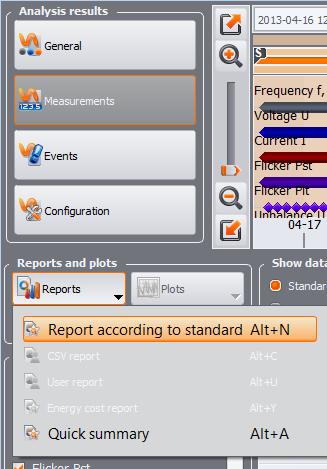
- How to generate a standard compliance report?
In order to generate a standard compliance report, the registration with normative data should be loaded into Sonel Analysis. Then, in the Measurements window, click on the Reports button, and then select the Report according to standard option.
<meta charset="utf-8" />
If the loaded registration does not have normative data, the Report according to standard option will be inactive (grayed out).
- What does class A analyser mean?
Class A (like Advanced) - instruments in this class are used when precise measurements are required. Especially in cases that may require settling disputes between the supplier and the energy consumer, checking complaints regarding compliance of the power supply with standards, etc. Measurements of parameters carried out using two different instruments meeting the requirements of Class A, when measuring the same signals, should give comparable results for this parameter (including measurement uncertainty). Thanks to this, any disputes should be limited to the subject of the dispute, and not to the tools with which the measurements were made.
Class A analysers must be able to synchronize time with a standard time signal to meet the requirements set for them. The time deviation throughout the measurement cannot be greater than +/- 20 ms for a 50 Hz network. Synchronization can be carried out using various technical solutions: GPS, DCF77, NTP. Due to the availability and precision, synchronization via the GPS module is most often used.
- What does the analyser class S mean?
Class S (like Surveys) - these are analysers used for statistical applications, such as statistical evaluation of energy quality with a limited set of parameters. Although Class S analysers use equivalent measuring ranges as Class A, the requirements for processing Class S data are much lower. Class S analysers are widely used in daily power quality measurements in buildings, industrial plants to ensure power continuity, etc.
- Analyzer measurement sampling
Sampling frequency in PQM analyzers is 10.24 kHz, which is equal to 204.8 samples per period for 50 Hz network and 170.7 samples per period for 60 Hz network. With this sampling frequency, analyzer generate the variable course of one 20 ms period from 205 samples in the 50 Hz network. That gives us good precision of conversion of signal from analog to digital, which is sufficient in everyday power quality measurements.
PQM analyzers are advanced measuring devices, equipped with high-class components and complicated measuring algorithms to meet the requirements of all users.
- What current ranges can be measured with PQM clamps and power quality analyzers PQM so that the measurement error of 30% is not exceeded?
Sonel PQM power quality analyzers measure the current using many types of clamps available in the offer. The table below shows which ranges of AC and DC current measured with given clamps will not be affected by measurement errors exceeding 30%.
Power quality analyzer
Clamp type
Current measurment working range 50/60 Hz (only basic error of clamp, maximum error of the measurement method = 30%)
PQM-700
PQM-707
C-4A
7,8 - 1000 A AC
C-5A
10,5 - 1000 A AC/DC
C-6A
0,078 - 10 A AC
C-7A
0,75 - 100 A AC
F-1A1, F-2A1, F-3A1
10,7 (10,5*) - 1500 A AC
F-1A, F-2A, F-3A
21,4 (21,1*) - 3000 A AC
F-1A6, F-2A6, F-3A6
42,8 (42,1*) - 6000 A AC
PQM-701
PQM-702
PQM-703
PQM-710
PQM-711
C-4A
4,1 - 1000 A AC
C-5A
7,0 - 1000 A AC/DC
C-6A
0,041 - 10 A AC
C-7A
0,41 - 100 A AC
F-1A1, F-2A1, F-3A1
5,3 - 1500 A AC
F-1A, F-2A, F-3A
10,7 (10,5*) - 3000 A AC
F-1A6, F-2A6, F-3A6
21,4 (21,1*) - 6000 A AC
* Applies to clamps with a 16-digit serial number containing the segment 10XY or higher.
- How long can the analyzers run on battery power?
It depends on the type of analyzer, the number of connected modules, environmental conditions and others. Generally, the working time is:
- PQM-700 - minimum 6 hours,
- PQM-701 (Z, Zr) - minimum 5 hours,
- PQM-702/710 - minimum 2 hours,
- PQM-703/711 - minimum 1.5 hours,
- PQM-707 - minimum 4 hours.
- Can Sonel analyzers measure DC current and voltage?
Yes, all analyzers are designed to measure DC voltages and currents. To measure DC currents, additional C-5A clamps are required.
- Can I insert a larger capacity card into the analyzer?
Analyzers with removable memory cards, PQM-700 and PQM-707, have the possibility of extending the memory up to 32 GB. If you want to change the standard 8 GB memory in the PQM-702 (T) / 703/710/711 analyzers, this possibility is up to 32 GB. For this purpose, this should be established when purchasing a new analyzer with your sales representative. In the case of an already purchased analyzer, please contact the export department [email protected]
- How to assign memory to a given configuration?
In the upper left part of the Analyzer configuration window, there is the Local panel. The first item in the panel is General Settings. In the main part of the window, one of the three tabs (Analyzer type, Memory allocation, GPS synchronization) is displayed. On the Memory allocation tab, use the sliders to change the percentage of memory assigned to each configuration.
<meta charset="utf-8" />
- How to change rates and hours of tariffs in Sonel Analysis software?
Press F9 to go to Program settings, and then go to the Data analysis tab. Select Energy Tariff Settings in the window on the left. Here you can change the tariff rates and the times of their validity.
<meta charset="utf-8" />
- Will the range and accuracy of the current measurement increase when making two turns with a flexible probe on a conductor?
By using two turns, we increase the accuracy of the current measurement, but at the same time we reduce the measuring range by half of the Inom value.
- Can the analyzers be used outdoors?
Yes, almost all Sonel analyzers have an appropriate housing design with IP65 tightness. The PQM-707 analyzer is an exception, as it is dedicated to indoor and outdoor measurements on a sunny day.
- What to keep in mind during registration with Sonel PQM analyzers?
There are many elements to remember before and after starting data registration. Below is a list of the most important ones that you must not forget:
- Correct configuration of recorded parameters. Choosing the right type of network and other parameters determines what type of data will be recorded.
- For current measurement, use appropriate clamps connected in the direction of the current flow "to the receiver", as indicated by the arrow on the clamp.
- Connecting the voltage cables and current clamps of one channel to the same phase.
- Choosing the right configuration in the analyser.
- Time and date verification on the device.
- Verifying the connection (error messages) and phasor charts.
- If possible, perform a trial registration and read the results.
If all of the above points have been completed, you can start the correct registration.
- What means the arrow on the current clamp?
The arrow on the clamp indicates the conventional direction of current flow. In Sonel Analysis software the conventional direction of current flow from the source to the receiver was adopted. This clamp orientation is required for correct measurement of power and constant components. When measuring the current in the Neutral wire, the arrow should also point towards the receiver, as on the other clamps connected to the phase wires.
- What does the letter "A" mean in the name of the clamp?
Clamps with the letter A at the end of the name (e.g. F-3A) are a variety of clamps with automatic detection of their type on compatible analysers. For such clamps, during registration configuration, you can select the clamp type "Auto".
- Are clamps with the letter "A" in the name compatible with clamps without the letter "A"?
Yes, for example, C-4 and C-4A clamps are the same and can be used interchangeably. The only difference is that the clamp with the letter "A" can be automatically detected by the analyser. It should be remembered that in order for the automatic clamp detection function to work properly in dedicated analyzers, a whole set of clamps with the letter "A" in the name should be used.
- What is the accuracy of my F-series flexible clamps? Is it 1% or 0.5%?
In response to customer expectations, the F-xA, F-xA1, and F-xA6 series clamps feature an accuracy of ±0.5% within the measuring range. Earlier versions were characterized by an accuracy of ±1%. To determine the accuracy of your specific clamps, please check the serial number on the label:
- For clamps with a 10-digit serial number, the accuracy is ±1% within the measuring range.
- For clamps with a 16-digit serial number containing the segment 09XY or lower, the accuracy is ±1% within the measuring range.
- For clamps with a 16-digit serial number containing the segment 10XY or higher, the accuracy is ±0.5% within the measuring range.
- What are the normative requirements for class A and class S analyzers according to IEC 61000-4-30?
Normative requirements for Class A and Class S analyzers according to IEC 61000-4-30 are shown in the table.
- How recorded results can be downloaded to analyzer?
To download recordings from analyzers, use latest version of Sonel Analysis software. Run software Sonel Analysis, connect analyzer to a computer and then:
- select the Analysis mode from left top Analyzer MENU,
- connect to correct analyzer and download and storage data from the device.
Sonel Analysis software allows you to download recorded data from all analyzers models and additionally also screenshots from the PQM-707 model.
More details user will find in the Sonel Analysis user manual and the PQM analyzer manuals.
- How to update the firmware of the Sonel PQM-700 analyzer?
Firmware update can be performed using the Sonel Analysis https://www.sonel.pl/en/product/software-sonel-analysis-4/ software.
An alternative way is to find the PQM-707 on the website https://www.sonel.pl/en/download/firmware/ in section Power Quality Analysis. The software file should be downloaded and unpacked onto the analyser’s microSD card.After inserting the card with the recorded software file into the analyzer, press the START button on the meter. More details can be found in the instruction manual. https://www.sonel.pl/en/download/user-manuals/ - How to update the firmware of the Sonel PQM-707 analyzer?
Firmware update can be performed using the Sonel Analysis https://www.sonel.pl/en/product/software-sonel-analysis-4/ software.
An alternative way is to find the PQM-707 on the website https://www.sonel.pl/en/download/firmware/ in section Power Quality Analysis. The software file should be downloaded and unpacked onto a USB flash drive and inserted into the analyzer. In the analyzer from the Main menu, enter Analyzer Settings -> Updates and follow the instructions on the screen. You can see more on the video presenting the entire procedure https://www.youtube.com/watch?v=1os1yvHyuWw&ab_channel=SonelS.A. - Uploading big datas from PQM-700, PQM-701 (Z, Zr) and PQM-707 analyzers via USB cable might take long time. Can it be accelerated?
In order to transfer more data (megabytes) from these analyzers to Sonel Analysis software, remove the microSD card from them and use in external microSD memory card reader slot. While reading data in Sonel Analysis, the device will appear on the recognize analyzers list with the note “Connection with memory card”.
Note: Only latest version SONEL Analysis software should be used to read data from the SD card - Do I need to buy a GPS receiver for time synchronization in class A analyzers?
Class A analyzers have a built-in GPS signal receiver with an internal antenna. This is sufficient for time synchronization if the analyzer is to be used outdoors. If the analyzer will be used indoors, it may be necessary to purchase an additional external antenna with a 10 m cable https://www.sonel.pl/en/product/gps-antenna-10-m-lead . The antenna should then be placed in an area with a GPS signal (e.g. outside a window).
- Why is the ERROR LED in the PQM-700 flashing and Irms is crossed out in the current readings? What does it mean?
A flashing ERROR diode in the PQM-700 analyzer may mean that one of the adopted criteria for assessing the correctness of the analyzer connection to the network indicates a potential problem. The red X sign next to the Irms parameter in the Phasor charts tab of the current readings in Sonel Analysis software indicates that the calculated sum of the phase and neutral currents is higher than 25% of the maximum value of the measured current for any measuring channel. As the sum of all currents (instantaneous values) is not zero. It is treated as an error and the ERROR LED is blinking. This helps in determining if all current probes are connected correctly, i.e. the arrows on the clamps are pointing towards the receiver.
- How to update Sonel Analysis software?
The update is performed automatically by the program itself, if the computer is connected to the Internet and its ports are not blocked, preventing the program from connecting to the update server (e.g. by anti-virus programs or firewalls).
An alternative way is to download the latest program installation file from the website https://www.sonel.pl/en/product/software-sonel-analysis-4/ and install it on your computer. - What current probes are included in the standard equipment of the analyzers?
The standard equipment of the PQM-707 analyzer are four F-3A flexible current probes (up to 3 kA). Other analyzers do not have any current probes as standard equipment. They should be selected from the wide range of current probes, which can be found at https://www.sonel.pl/en/products/accessories/clamps .
There may be temporary commercial promotions, offering extended accessories as standard. Check the details with your local distributor.
- What are harmonics?
The AC supply voltage and the resulting load current in the 50 Hz network have a sinusoidal fundamental component of the same frequency. However, depending on the non-linearity of the receiver and many other factors, the actual shape of the current may not resemble a sinusoid. However, it can be replaced with a set of component currents with frequencies that are natural multiples of the fundamental frequency. Each of these currents influences the supply network in a different way, creating harmonics in the voltage. These additional voltage harmonics feed all devices connected to this network. In this way, each device powered from this network may (usually unfavorably) affect the operation of other devices.
- What is the inrush current?
Every electrical device to work must first start this process. When switching the device on, the current flow appears, which is even more than a dozen times the rated current of the device. This can cause various negative effects on the electrical network. The inrush current can be recorded with PQM series analyzers and on this basis it is possible to determine the specific features of the start-up, which is necessary especially when selecting appropriate protections.
- What is the average, minimum, maximum and instantaneous value in the recorded data?
The analyzer samples the signal at a certain sampling rate and creates data blocks with a length of 10 periods (which for a 50 Hz mains frequency is a 200 ms block). From these blocks, the average value is calculated for the averaging interval selected by the user (e.g. for the averaging period of 5 seconds, the average value will be calculated from 25 blocks of 200 ms). The minimum and maximum value are the two limits in the averaging period. The instantaneous value is the value of the last 10-period block in which the averaging period has ended.
- How to read live data?
- Locators of cords and cables, fault detection
- How to use LKZ-700 wire tracer?
Please check our video about LKZ-700 - is available on our youtube channel.
- Routing of a cable when only one end is available with LKZ-700 wire tracer
When the cable is not damaged and the circuit is live, use the magnetic field method (receiver and transmitter in "M" or "I" mode). Then connect one transmitter conductor to the phase conductor and the second to the PE cable in the farthest location (PE cable in another room, earthing, grounded metal pipe for the heating system ...). The receiver detects a signal in places where the cable is located.
In an undamaged circuit without voltage, connect the transmitter conductor to N wire, while the second to another, distant earthing, and select the current-voltage mode (transmitter in the "E + M" or "U + I" mode and the receiver in the "M" or "I" mode).
It is possible to connect both transmitter conductors to N and L conductors of one socket, but remember that signals flowing through L and N (depending on the arrangement of conductors) will more or less reduce each other, and the signal level indicated by the receiver may vary, misleading operators inexperienced in locating wires.
- Routing of a cable with a broken conductor with LKZ-700 wire tracer
Set the transmitter and receiver at the voltage mode ("E" or "U" marking) and connect it to the tested conductor. Other conductors in the cable and the other end of the broken conductor (when you have an access to the other end of the cable) must be grounded to prevent the penetration of electric field. The receiver will show the signal level as long as you move it over the cable route - up to the point of damage.
Due to the applied electric field (susceptible to damping), the method is not recommended for locating cables (depth too large = significant distance from the cable generating the field).
- How to use LKZ-700 wire tracer?
- Portable appliance testers / safety of electrical equipment
- What PAT should you choose for welding machines?
A suitable meter for checking welding equipment is PAT-806.
- PAT series: What is the difference between two types of leakage current?
A Leakage current is a current that flows from live parts of a device, through isolation, to the ground. PAT meters provide the measurement of four types of leakage current:
- Replacement leakage current: current is measured after applying voltage between shorted L and N and PE (Class I devices) or a probe in contact with the device housing (Class II);
- Ground leakage current: only current flowing through PE conductor of the tested device is measured (the leakage through other routes is not measured);
- Differential leakage current: the difference between current flowing through L conductor and the current flowing through N conductor is measured - taking into account all current leakage routes;
- Touch leakage current: the leakage current is measured by taking into account human perception and response in accordance with PN-EN 60990 (internal resistance of the test probe = 2kΩ).
Detailed description of the above measurements is presented the guide entitled "Testing the safety of electrical equipment" available on our website.
- What does the Udt message on the meter mean?
Such a message means that the tested receiver has a voltage which should be disconnected before making the measurement.
- What PAT should you choose for welding machines?
- Thermal imagers & pirometers
- I have a battery problems with thermal camera KT series
Batteries in KT series cameras charging without having to remove them from the camera - just plug in the AC adapter to the camera and turn off the camera. If the battery is completely discharged (for example, after a long period of inactivity), and every 5 charges (in order to extend their life - because of the series connection of the camera) it is recommended to carry out an external charger, charging each cell independently.
New batteries should be three-fold completely discharged, then charged in an external charger to form - it also provides the increased viability (after recharging can take place at any time).
If the camera is to be unused long time, it is recommended that every few weeks recharge the batteries. When not using the camera, batteries should be removed from the camera. - What is the maximum distance for temperature measurements with a thermal imaging camera KT series?
Theoretically, the distance is infinite, but in Earth conditions the stratosphere is the limit (several kilometres), hence the cloudless blue sky is "colder" than the clouds.
However, other parameters must be also considered, e.g. minimum size of the object being measured in terms of measuring distance, the resolution of camera matrix and the lens used.
- I have a battery problems with thermal camera KT series
- Illuminance measurements meters
- What is the difference between the luxmeter, marked with the information "dedicated to LED measurements” from the Sonel luxmeter LXP-2/10B/10A?
They can differ only in the additional possibility of introducing a correction factor previously defined on the basis of calculations referred to in the CIE-127:2007 commission report. This applies when there is no correction in the given luxmeter. It should be noted that discharge light sources, e.g. sodium or xenon, have characteristics strongly divergent with the curve of the CIE standard and yet lighting with these sources does not raise any doubts as to the functional characteristics.
- How often should you calibrate the luxmeter?
There is no specific time after which the luxmeter must be re-calibrated. Calibration certificates issued by the Central Offices of Measures or accredited calibration laboratories do not specify the validity date of the calibration. The user of the measuring instrument determines the dates of repeating the calibrations. It should be noted, however, that the photovoltaic cell being a sensor is aging, so it should be subjected to periodic metrological control. Having a valid calibration certificate for a luxmeter confirms the device's efficiency and its declared levels of spectral and basic uncertainty. Often, the employer requires a calibration certificate of the measuring device to be attached to the measurement documentation.
- Why is it worth to make periodic measurements of lighting? Benefits of good lighting.
• the effect of good lighting on the well-being of working people and the achievement of a higher level of production in terms of quantity and quality,
• reduces the risk of an accident at work,
• affects the well-being and pleasant feelings of a man in a specific room,
• facilitates proper selection of colors (this is of special importance eg in production plants, offices, schools),
• prevents the need to strain the eyesight, and thus premature weakness,
• facilitates the operation and maintenance of production machines and devices,
• improve transport within the factory.
- Are the Sonel LXP-2/10B/10A luxmeters suitable for measuring the illuminance of LED light sources?
Yes. Currently, there are no clearly defined requirements regarding the measurement of LED lighting sources. The International Lighting Commission issued in 2007 only a report (http://www.cie.co.at/publications/measurement-leds) containing recommendations for testing LED lighting with division into white and color light emitted. More in the article
- How often should I measure the light intensity?
Lighting, unlike other factors in the field of noise and dust, is not a dangerous physical factor in the work environment, but is classified as a nuisance. There are no specific regulations in which periodic measurements should be made.
The employer is obliged to provide electric lighting with parameters compliant with the Standard EN 12464-1 Light and lighting - Lighting of work places - Part 1: Indoor work places.Measurements of illuminance are made:
- when creating jobs,
- after modernizing the lighting at the workplace or adding a new light source.
The employer decides about the frequency of lighting measurements. However, taking into account the employee's good, often the measurements of lighting are carried out together with checking the electrical installation. However, measurements of electrical installations are required and should be carried out in every construction facility every 5 years.
- What is the difference between the luxmeter, marked with the information "dedicated to LED measurements” from the Sonel luxmeter LXP-2/10B/10A?